WiFi Controlled Dimmable LED Lights for Camper Van
After a bit of a summer break here on the blog, we are back with more content. This time, we want to show you how we are controlling the LED lights in our camper.

You will learn about:
- LED strip lights,
- Our self-designed controlling circuit board,
- How LED dimming works,
- The Homie convention; and
- Our home automation system
If you are interested in our electrical system and electronics, we have a video dedicated to electrics!
LEDs perfect for off-grid
Adding light to your camper is not that difficult. There are a lot of products on the market designed to run off 12 V batteries. Many van lifers use puck/pot lights and connect them to simple switches or dimmer switches. With the advent of LED lights, the light industry made a huge step towards efficiency. Where in the olden days you'd run halogen lamps with 20 W each, but only get a lousy 20 lm/W at best, LEDs, on the other hand, provide an astonishing 100 lm/W. They are 5 times more efficient than incandescent light bulbs.
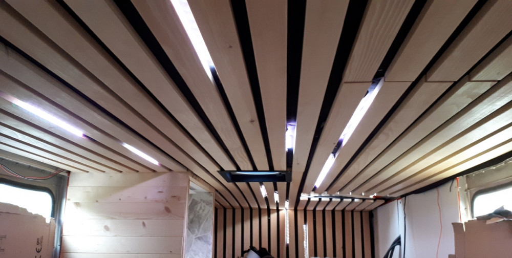
Before we built our ceiling, we knew that we wanted to integrate lights into our ceiling. Sorry we don't have the ceiling blog post ready just yet, but you can already watch that project in our YouTube videos. With that in mind, we chose LED strips. You will find a vast number of these strips, so let's narrow down what we needed:
- Should run off 24 V
- We want color, so they'll need to have RGB LEDs
- We want the whole spectrum of white to wam lights for video and function
- They need to be bright enough (more white LEDs?)
We ended up with a 24 V, RGB, W and WW LED strip (red, green, blue, white and warm white).
Now, how will we control all these LEDs? Most commonly, RBG controllers have tiny infrared remotes which lets you choose from colour presents. However, most of these are not suitable for 24 V and even fewer could control all five LEDs on our strips.
How to control 12 LEDs?
Finally, this encouraged me to challenge myself with a project I've had in my mind for a long time: build a circuit board and have it professionally manufactured. Not too long ago, hobbyists had to work with dangerous chemicals, transparent printouts, and darkrooms to etch their own circuit boards. The times have changed and now, you can get an entire batch of professionally etched, multilayer circuit boards for a few dollars apiece. These boards though, you'd still have to assemble yourself. You'll need to buy the components and solder them onto your board piece by piece.
It is 2020 and now, there are PCB manufacturers who offer PCB assembly at very reasonable prices. Even a hobbyist like me can afford a fully assembled and e-tested circuit board.

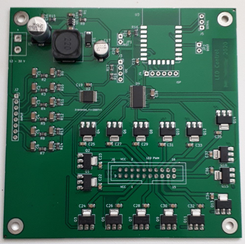
I designed my own 16 channel PWM LED controller with 6 digital inputs, so that we could add traditional light switches. All the work was done in KiCAD and with the help of an additional tool, I could generate the parts list and the positioning list for the pick and place machine at the PCB factory.
The board has the following specs:
- Input voltage: 12 - 48 V
- Current per channel: 2 A
- Resolution per channel: 4096 bits
- PWM frequency: 24 - 1526 Hz
- Digital Inputs: 12 - 48 V
I wanted to be able to hook up the controller to our home automation system, so we landed on an ESP8266 microcontroller (the brain) as the choice. This tiny computer—the size of a pinky fingernail—runs at 160 MHz. The biggest benefit is it offers WiFi connectivity which lets me connect it to OpenHAB, a home automation system, running on a Raspberry Pi.

How dimming LEDs works
In the simplest case, you can change the current flowing through the LED and this will result in a brighter or less bright light. Computers are very bad at analog output; their inner workings are digital after all—either 1 (current flows) or 0 (no current flows). The trick to dim LEDs is to switch your LEDs on and off very quickly—it's not so much dimmed light as it is flickering lights to appear to be dimmed. With my current setup, I switch them at 200 Hz, so 200 times every second. But that's only half the way there. If you turn them on for 5 ms and turn them off for 5 ms, you will get about half the current flowing than if you'd leave the LED on all the time.
Here is where PWM—pulse width modulation—comes into play. You have your base frequency of 200 Hz. Within the periodic signal you change the so called duty cycle, which is the time in when current flows. For the rest of the period, it doesn't flow. This ultimately lets the LED appear brighter or less bright. A PWM is usually implemented with a counter which will count from, for e.g., 0 to 4095. Once it reaches 4096 it flips back to 0. You then set a variable to, for e.g., 1024. The counter counts, reaches 1024 and turns on the output. When it flips back to 0 it also turns off the output. The speed of the counter defines your base frequency. The number at which you switch defines your duty cylce.

The last piece you need to know is the human's eyes' preception of light. We are able to see with almost no light available, but we can also handle the sun burning down around noon. The light intensity is preceived almost logarithmically by the eye. A light that's burning at twice the power than its neighbour will only appear somewhat brighter. Scientists have described this in Stevens's power law, which describes how your body perceives physical stimuli.
I implemented a function with the help of Stevens' power law which would take the human input—dim the light to 60%—and convert it to a duty cycle for my PWM.
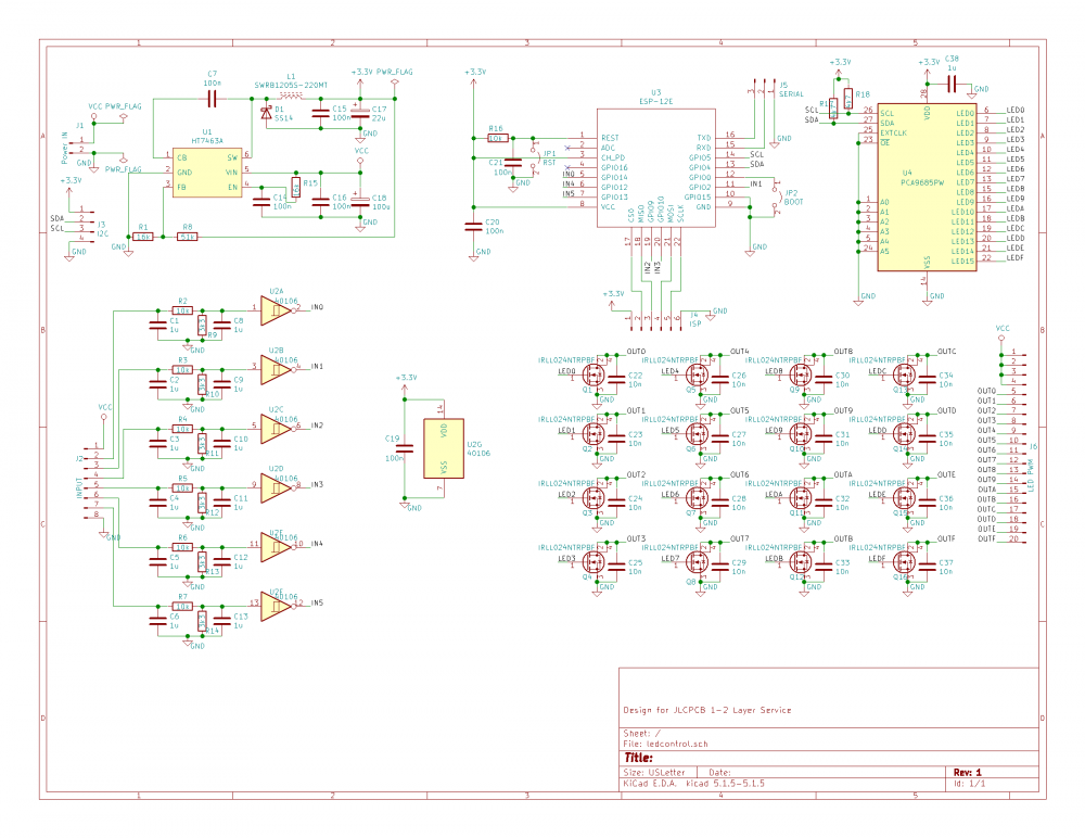
An IC (PCA9685) designed to output 16 different channels of PWM signals is connected to the microcontroller. That IC in return controls a set of 16 MOSFETs (IRLL024N) which amplify the signal, so we can switch our 60 W LED strip. Adding a few more components like a power supply (HT7463A) to convert the input voltage to 3.3 V for the microcontroller and a Schmitt-trigger (CD40106) for the digital inputs, along with a bunch of passive components to filter out unwanted interfering signals, and now, you've got yourself an LED dimmer with wireless connectivity.
Connect it to OpenHAB
To integrate the controller into a home automation system, you need to use a standard which both the controller board and the automation hub understand. A very simple implementation is the Homie convention. Requests are sent on a network bus (MQTT) to be executed by the LED controller. The controller itself registers itself to the bus by telling the automation system what its capabilities are.
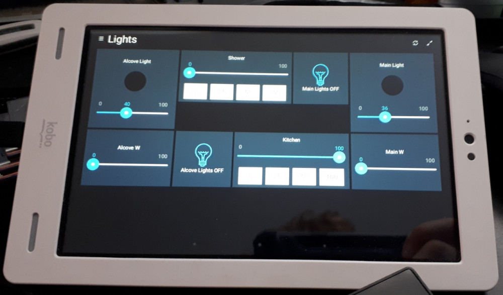
For example, I am telling our automation system that we have 2 RGB lights (alcove and main area), 2 white lights for the alcove and the main area each, a light for the shower, and a light for the kitchen. I also tell it that we have 6 inputs. With these instructions, we can later create actions whenever a button is pressed. All these messages are sent over the network but stay locally in the camper. There is no need for an internet connection for this to work.

The last piece is the home automation system itself. If you don't rely on cloud services, the easiest way is to use a Raspberry Pi in conjunction with OpenHAB. This is a software collection which has a wide variety of protocols and connectors all around IoT devices. On top of it all, it allows you to create dashboards so you can control all your devices. And of course, it lets you automate things. Thanks to the Homie convention, the LED dimmer registers automatically and there is very little configuration work on your side.
If you are curious about the source code of this project, I've bundled it into an archive here: ledcontrol.zip
It is written in Lua for the NodeMCU firmware and can be programmed onto the microcontroller using a serial interface. Be aware that the microcontroller is not 5 V tolerant, so you must have a serial adapter with 3.3 V signal levels! Please understand that I don't want to hand out the PCB design at this moment. One reason is that this is by no means a professional project just yet. I'll need to do more testing to satisfy EMC regulations. Also, my design had a routing error, so I had to pull a bodge wire from one pin of the microcontroller to the other. Feel free though to use the schematic or code for your own personal needs.
Johno
Johno